The design of electric vehicle battery packs may vary among manufacturers but commonly, the battery is attached to its cooling plate not only with fasteners but also thermally conductive polymeric materials called gap fillers. Gap fillers can outperform thermal pads in this application to achieve lower thermal impedance, as the gap fillers conform to surface roughness before curing. This allows gap fillers to adhere well to surfaces, provide mechanical support during normal operation, and pass strict reliability standards of OEMs. However, the high adhesion values also pose a challenge if the battery needs to be disassembled.
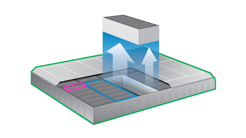
A general design of the battery pack is shown in Figure 1 where battery modules are tightly packed together to maximize space and energy density. Such tight assembly of batteries in their housing does not allow easy access for removal, such as peeling the battery from an edge, and vertically.
The reworkability of a battery pack entails removing and replacing the defective battery module without destroying the other modules or cooling plate. The stress required to remove a battery module depends on the adhesive strength of the gap filler, which in turn depends on the surface properties, mechanical strength of the gap filler and battery removal conditions. One may ask the importance of reworkability in the EV market. Aside from a clear environmental impact of a reworkable battery pack that allows reuse and recycle to reduce waste and encourage sustainability, there are real economic impacts.
Adhesive Failure Modes
In the box plots shown throughout the next few paragraphs, the arrows indicate an increase (red) or decrease (green) in the mean pull-off stress when moving from left to right CoolTherm® gap filler sample. A paired t-test for sample means is performed with alpha of 0.05 to evaluate if the difference in pull-off stress means is statistically significant. The failure modes are shown through a representative image alongside each box plot. The failure modes are defined as follows:
- Cohesive (coh): distinct failure in the bulk of the gap filler, both substrates have gap filler present. b. Adhesive (adh): failure at the interface between the substrate and gap filler, gap filler present only on one surface.
- Mixed (mix): a mix of adhesive and cohesive failure where some part of substrate is clean of any gap filler.
- A cohesive (coh) material failure is preferred by some OEMs from a thermal transport perspective. However, an adhesive (adh) failure is easy to clean. As we will see below, failure mode of a gap filler is not only a material property but also a result of the substrate surface.
For more information on our testing method and an illustration of our t-bar test samples, download the full white paper here.
Three Factors that Impact Gap Filler Reworkability
1) Surface Effects on Pull Off Stress
To evaluate the effect of rough surface on the pull-off stress, the T-bar surface was sand blasted. The surface roughness was measured using a surface roughness tester (Mitutoyo, SurftestSJ-210) as per ISO1997. The average roughness (Ra) for the clean aluminum surface was recorded as 0.35 ± 0.05 µm, whereas for the sand blasted surface the Ra was recorded as 4.66 ± 0.30 µm.
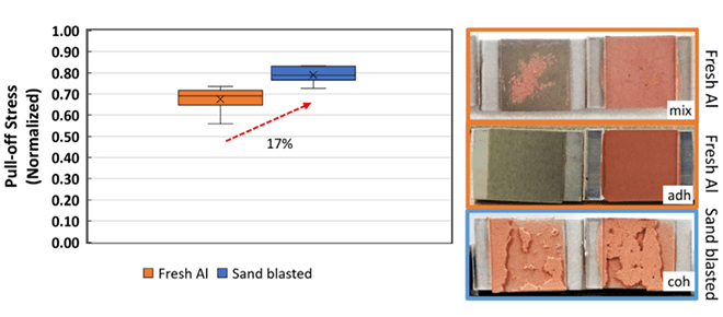
The surface roughness after sand blasting is roughly 10 times higher than the original surface. The vertical pull-off stress for fresh aluminum (fresh Al) and sand blasted is shown in Figure 2, where a 17% increase in the mean pull-off stress is observed for the sand blasted surface. The difference in mean values is statistically significant.
The failure mode also switches from adhesive/mixed (adh/mix) for fresh Al surface to cohesive (coh) for sand blasted surface as seen from the images in Figure 2. The result highlights the importance of defining substrate surface roughness while testing the vertical pull-off for reworkable gap fillers.
To explore our other tests on surface effects such as first-use versus second-use aluminum and the effect of e-coat on pull-off stress, click here to read the full white paper.
2) Effect of Pull Rate
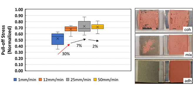
With the viscoelastic behavior of polymers in mind, the effect of pull-rate (strain-rate) on the pull-off stress was measured and the result is shown in Figure 3. The bond gap is kept constant at 1 mm. Clearly, the pull-off stress increases as the pull-rate increases. However, after 12 mm/min a less significant increase in pull-off stress is noticed for the tested gap filler. A noticeable difference in the failure mode is evident. At 1 mm/min, failure mode was cohesive (coh). At and above 12 mm/min, the failure mode was mostly adhesive (adh) with occasional mixed (mix). See this demonstrated in the figure below.
3) Effect of Bond Line Thickness
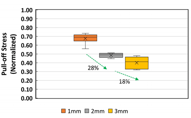
The next variable we investigated was the effect of bondline thickness on the pull-off stress (Figure 4). The pull-off stress decreases as the bond gap is increased from 1 mm to 3 mm. The failure mode switched from adhesive/ mixed (adh/mix) at 1 mm to completely adhesive (adh) for 2 and 3 mm bond gap.
Industry Considerations
If a battery can be pulled vertically from an edge, it may provide more than 50% reduction in the pull-off stress as compared to force being evenly applied from the center. The failure mode for our tested CoolTherm® gap filler was completely adhesive (adh) when pulling from an edge versus adhesive/mixed (adh/mix) when pulling from the center.
The tight assembly of battery modules may not allow for the peeling of the module from an edge. But, is a complete peeling from an edge required? The average displacement of the edge before joint failure was only 0.6 mm when pulling from the edge That equates to the angle of 1.4 degrees. If that angle of 1.4 degrees is applied to a battery module of usual size (40 cm x 20 cm), it results in the need for a 4 to 5 mm clearance between modules to allow for easier removal. This could reduce the required force by more than 50% as compared to lifting from the center or applying equal force across the surface of the module. This would significantly reduce the chance of damaging the cooling plate.
Looking for More Info?
Are you considering reworkability when designing your EV battery pack? Talk with a member of Parker LORD’s team for more information on this topic, read the full study here or visit lord.com/CoolTherm for product information.