Abstract
In both biological and engineered systems, functioning at peak power output for prolonged periods of time requires thermoregulation. Here, we report a soft hydrogel-based actuator that can maintain stable body temperatures via autonomic perspiration. Using multimaterial stereolithography, we three-dimensionally print finger-like fluidic elastomer actuators having a poly-N-isopropylacrylamide (PNIPAm) body capped with a microporous (~200 micrometers) polyacrylamide (PAAm) dorsal layer. The chemomechanical response of these hydrogel materials is such that, at low temperatures (<30°C), the pores are sufficiently closed to allow for pressurization and actuation, whereas at elevated temperatures (>30°C), the pores dilate to enable localized perspiration in the hydraulic actuator. Such sweating actuators exhibit a 600% enhancement in cooling rate (i.e., 39.1°C minute−1) over similar non-sweating devices. Combining multiple finger actuators into a single device yields soft robotic grippers capable of both mechanically and thermally manipulating various heated objects. The measured thermoregulatory performance of these sweating actuators (~107 watts kilogram−1) greatly exceeds the evaporative cooling capacity found in the best animal systems (~35 watts kilogram−1) at the cost of a temporary decrease in actuation efficiency.
INTRODUCTION
In certain mammals, the ability to lower body temperature via perspiration and evaporative cooling permits greater endurance during strenuous activity. This evolutionary adaptation, coupled with relative hairlessness, likely enabled early humans to excel as “persistence hunters,” capable of exhausting prey over a prolonged chase despite a comparatively slower top speed (1). Sweating takes advantage of water’s large enthalpy of vaporization (ΔHvap ~ 40 kJ mol−1), and perspiration rates (in humans) of up to 3.5 liters hour−1 correspond to roughly 2.4 kW of cooling capacity (2).
In engineered systems, the conversion of stored energy into useful work is never fully efficient, and heat is dissipated into the system. Adverse effects resulting from excess heat are numerous and include thermal expansion, stresses from temperature gradients, or a change in electron mobility in circuitry. Therefore, stable device performance requires proper thermal management, like the incorporation of sinks that absorb and dissipate heat through conduction, convection, and radiation. The practical implications of thermoregulation restrict available designs and limit the maximum achievable power densities of components. Recently, Kozuki et al. demonstrated a humanoid robot capable of artificial perspiration of water through a porous aluminum skeleton that dissipates ~0.9 W cm−2 of heat (3, 4). This efficient cooling enables the sizeable robot (>50 kg) to continuously do repetitions of “push-ups” for more than 11 min without motor failure (3).
The emerging field of soft robotics offers animal-like motions via continuum actuation and conformal interactions with the environment via compliant materials. An interesting application of these systems is for safe interfacing between robotic components and human tissues (5). Despite the use of actuation systems that release considerable heat (adiabatic compression, exothermic decomposition of peroxide fuels, and combustion of hydrocarbons) or actuation driven by elevated body temperatures (resistive heating and phase transition), few soft robots contain dedicated features for cooling (6–9). Unlike metals, many elastomer systems have a greater coefficient of thermal expansion (αsilicone ~ 10*αaluminum) and a lower coefficient of thermal conductivity at ambient temperatures (κsilicone ~ 0.2 W m−1 K−1 << κaluminum ~ 200 W m−1 K−1) (10). In addition, for elastomeric gels, temperature fluctuations may alter the volume of entrapped liquid phases. Because the Young’s modulus, E, in cross-linked rubbers is proportional to the volumetric cross-link density, ν, such deviations and other temperature effects affect mechanical performance (see section S1 for details). Soft robots operate by controlling strain differentials, and the variance in shape and stiffness from thermal fluctuation threatens the reliability and precision of these devices. To support the advancement of soft robotics into high power autonomy, thermal regulation systems compatible with their mechanisms must be developed (11, 12).
Here, we demonstrate a hydraulically actuated soft machine, a hand, that thermoregulates via autonomic, localized sweating through microscale pores. Unlike previously reported hydraulically actuated soft manipulators (13), our hand incorporates dynamic pores that change dimension with temperature and high surface area texture that enhances evaporative cooling. We fabricated the fingers of this hand using a custom-built multimaterial stereolithography (SLA) three-dimensional (3D) printing (14–16) approach to selectively photopolymerize finger-like actuators composed of two hydrogel materials with distinct responses to temperature—a poly-N-isopropyl acrylamide (PNIPAm) actuator body that is capped with a porous polyacrylamide (PAAm) layer. At low temperatures (T ≤ 30°C), the fingers of the hand perform like a typical fluidic elastomer actuator. At higher temperatures (T > 30°C), the PAAm layer expands, causing the pores to increase their diameter, resulting in the pressurizing fluid “sweating” out of the actuator. Our autonomically perspiring system cools the actuator via evaporation, yielding an ΔT ~ 21°C reduction in the surface temperature of these functionally graded actuators within 30 s when the actuating fluid temperature is Thyd ~ 70°C.
Material design for autonomic perspiration
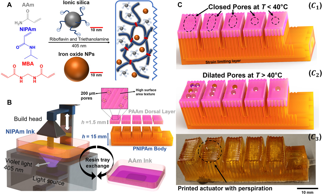
Hydrogels are water-soluble polymer networks that are ideal materials for soft robotics owing to elastic moduli spanning the regime of many soft biological tissues (1 kPa < E < 10 MPa). Gel systems with large volume fractions of water can act as heat reservoirs to delay the onset of thermal damage (17, 18). Initial hydrogel-based actuators were osmotically driven “smart gels” that change shape by absorbing or expelling large amounts of solvent in response to environmental stimuli (19). Acrylates [CH2═CH(C═O) O─R] are ideal components in custom hydrogel inks due to the large number of commercially available species and their ability to participate in both photo-initiated and thermally initiated free-radical polymerization (20). The varying side groups (─R) determine thermodynamic compatibility of material with solvent. For example, aqueous solutions of NIPAm have a lower critical solution temperature (LCST); the isopropyl moiety attached to the acrylate group induces hydrophobicity, or a miscibility gap, when T ≥ 30°C. Although the hydrophilic amide group in AAm is not as temperature sensitive, the addition of AAm to a NIPAm solution improves the aqueous solubility, raises the LCST, increases polymerization rate, and strengthens the resulting copolymer. We chose to develop two hydrogel inks: one composed of AAm monomers and a copolymeric ink composed of both NIPAm and AAm monomers in a 3:1 molar ratio. As shown in Fig. 1A, we also incorporated iron oxide and silica nanoparticles into our ink formulations to reduce build times and increase the mechanical integrity of printed devices as previously demonstrated (21).
(A) Chemistry of ionic composite hydrogels via photopolymerization of AAm and NIPAm in the presence of sulfonate-modified SiO2 and Fe3O4 using riboflavin photoinitiator, triethanolamine co-initiator, and MBA as a cross-linker. (B) Simplified architecture of the SLA 3D printer with resin replacement mechanism and exploded view of the actuator, which constitutes multimaterial layers; pink color represents the PAAm, brown color constitutes PNIPAm, and h represents the height of PAAm and PNIPAm body. (C) 3D-printed actuator with high surface area and multimaterial design. (C1) Actuator with pore design, texture, and strain-limiting layer. (C2) Animated model showing perspiration. (C3) 3D-printed actuator that resembles the animated model.
3D printing can simplify the manufacturing of soft robots while simultaneously achieving sophisticated mobility and manipulation (20). SLA is a light-based 3D-printing technique that uses controlled photoirradiation to selectively cure an object from within a vat of liquid photopolymer ink. In bottom-up SLA (Fig. 1B), after each layer photopolymerizes, the build head translates vertically, and our low apparent viscosity ink (ηapp < 10 Pa s) flows to replenish the build area. Then, the next layer is illuminated, and this process iterates. SLA permits both micrometer resolution and rapid deposition rates (>106 mm3 hour−1) due to the spatial-temporal resolution of light and the ease of scaling photo-patterns (20). To allow us to print two types of hydrogels, we used SLA combined with “vat replacement” strategies (Fig. 1B and movie S1) for functionally graded actuators (16, 22).
Using the high-resolution capabilities of SLA, we printed micrometer-scale pores within our hydrogels (Fig. 1C) to facilitate perspiration for rapid cooling. Unlike static pores that would perspire at a constant flow rate at a given pressure, our pores change cross-sectional area due to the hydrogel swelling or shrinking in response to local temperature. This behavior not only is necessary for pore constriction to minimize pressure loss during hydraulic actuation but also amplifies the perspiration rate local to where elevated temperature is occurring, akin to focal hidrosis in mammals. Beyond controlling the perspiration rate, our actuators also improve evaporative cooling through high surface area texturing (Fig. 1C and fig. S1, A and B) on the order of human skin (19, 20). To understand and control our actuator’s thermoregulation, we investigated the complex thermal response of multiple pore geometries fabricated from both our hydrogel materials.
RESULTS
Hydrogel material characterization
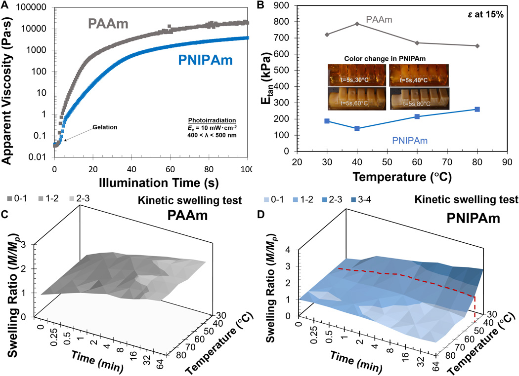
First, we developed two custom aqueous inks based on AAm and NIPAm monomers, a previously reported aqueous photo-initiating system (21), and cationically functionalized nanoparticles (see Materials and Methods). Photo-rheology (Fig. 2A) shows that both ink materials have low initial apparent viscosities that aid in rapid replenishment of the build layer during SLA printing and an immediate increase in viscosity and elasticity upon illumination. We can quantitatively infer the gel point, or liquid to solid transition, from the crossover in storage and loss modulus during photo-exposure (fig. S2, A to D). The AAm-based resin gels in under 80 mJ cm−2, and the NIPAm-based resin gels in under 175 mJ cm−2 of radiant exposure, He (λ = 400 to 500 nm). Because many commercial SLA printers supply a continuous radiant flux, Je, of 20 mW cm−2 or greater, these results suggest exposure times per build layer on the order of 10 s or less (He = Je·t).
(A) Apparent viscosity ηapp of AAm and NIPAm solution (plotted data are the average of N = 3 trials). (B) Tangent modulus, i.e., the calculated slope in the stress-strain curve at 15% compressive strain, for PNIPAm and PAAm at different temperatures (shaded regions represent SE in the line of best fit; error bars are SD; N = 7). (C) Gravimetric swelling ratio of 3D-printed PAAm sample versus temperature and time (plotted data are the average of N = 7 concurrent samples). (D) Gravimetric swelling ratio of 3D-printed PNIPAm sample versus temperature and time (plotted data are the average of N = 7 concurrent samples).
The initial resin composition is 50% (by weight) water, but both materials can absorb or desorb additional water molecules from their environment to swell or contract from the printed geometry (see section S2 for more details). Our two hydrogel materials display opposing changes in modulus as the temperature changes from 30° to 80°C and good cyclic performance (Fig. 2B and fig. S3, A to D). The PAAm-based gel softens over this regime, likely due to modest solvent uptake and an increase in molecular mobility above glass temperature (Tg). Comparatively, heating stiffens the PNIPAm-based material due to an increase in the effective cross-link density as the network expels water above the observed LCST. This conformational change with temperature in the PNIPAm material is immediately visible as a color change (Fig. 2B, inset, and movie S2). The swelling experiments plotted in Fig. 2 (C and D) further confirm this behavior. The gravimetric swelling ratio (mass/massprinted) for PAAm is relatively consistent at long time scales, less than 3% higher at 80°C than 30°C. PNIPAm, however, collapses at 80°C to less than 30% of its swollen mass at 30°C (see fig. S4A). To understand the thermodynamic properties of our 3D-printed hydrogel, we used differential scanning calorimetry (DSC) to measure the specific heat capacity (C, J kg−1 °C−1) and physical property measurement system for measuring the thermal conductivity at different temperatures for PAAm and PNIPAm. For example, the heat capacities at ~50°C for PAAm and PNIPAm are both ~0.12 J °C−1, respectively. The thermal conductivities are 0.46 W m−1 °C−1 (PAAm) and 0.40 W m−1 °C−1 (PNIPAm) at ~50°C. All data are reported in fig. S4 (B to D), and sections S3 to S6 include more details.
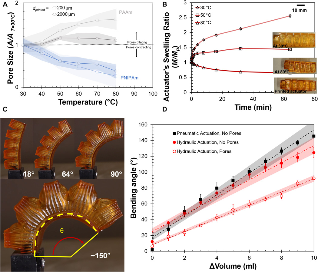
Bioinspiration suggests mimicking the sweating mechanisms found in human skin by directly fabricating circular pores that vent the internal fluidic channel of the actuator. However, if the pores are too large, the pressure gradient that drives such fluidic elastomer actuators will fail to develop and render the device useless. Thus, optimal pores will be sufficiently small at low temperatures to allow pressurization and sufficiently dilated at elevated temperatures to allow cooling. Figure 3A shows the change in pore area (A/A0) for our two hydrogel materials as a function of temperature for two initial pore diameters: 2000 and 200 μm. At 200 μm, the minimum negative feature size for our fabrication method, the PAAm pore area at 80°C is 60% greater than that of ambient conditions. Figure 3A (see also fig. S5, A and B) suggests that a reduction in the total pore volume—i.e., reducing pore diameter while holding layer thickness constant—corresponds to a greater change in pore area with temperature. This result is unsurprising because hydrogel swelling is a volumetric phenomenon. Unfortunately, the temperature response for pores within the PNIPAm-based material is opposite to our desired goal; pores close above 40°C (see also fig. S5, A and B).
(A) Pore size variation of PAAm/PNIPAm samples with different diameters and temperatures (shaded regions are SDs; N = 7). (B) Volumetric change in actuator at different temperatures and time. (C) Pneumatically actuated hydrogel actuator to attain maximum bending angle. (D) Bending angle versus input volume, actuator tested by water and air with different actuator designs (error bars mark the SD; N = 3; shaded regions represent SE in line of best fit).
It is also desirable that the body of the actuator does not expand with increasing T, because this expansion may allow the actuator body and its fluidic channel to accommodate a larger volume of water and consequently reduce flow of water through the pores. Thus, Fig. 3B depicts the PNIPAm-based body shrinking to squeeze water from the fluidic channel through the expanded AAm-based pores when temperatures exceed the LCST. The actuator volume at 80°C is 25.4% smaller than the volume at ambient. The swelling response of these pores is reversible (see fig. S5C).
Actuator design and performance
The excellent photopolymerization behavior of our resins enable the SLA printing of textured finger-like actuators with embedded fluidic channels for pressurization and pleated structures that increase actuation amplitude (23), as shown in Fig. 3C. When the 200-μm pores are printed within the actuator, a bending angle of θ < 80° is obtained at relatively low actuation volumes of room temperature water (Fig. 3D). Although this is much less than the actuation angle of the nonporous actuators, which can obtain similar actuation angles at 25% the actuation volume, it is still sufficient for many soft robotic applications. These nonporous hydrogel actuators have such low stiffness as to be actuated 150° at pneumatic pressures as low as 6 kPa (see figs. S5, D and E, and S6 and movie S3). Such low driving pressures enable a greater number of actuation cycles from a given reservoir for greater endurance in untethered operation.
Evaporation is a surface phenomenon. For that reason, we theorized that a textured actuator with a high surface area will exhibit faster evaporation rates than an equivalent lower surface area body. By adding texture (triangular tooth shape, ~1-mm pitch, 0.5-mm valley height) features onto the computer-aided design (CAD) model before printing, we achieved a 15% enhancement in evaporation rate (section S7 and fig. S7). We used these textured surfaces in the remaining actuators reported.
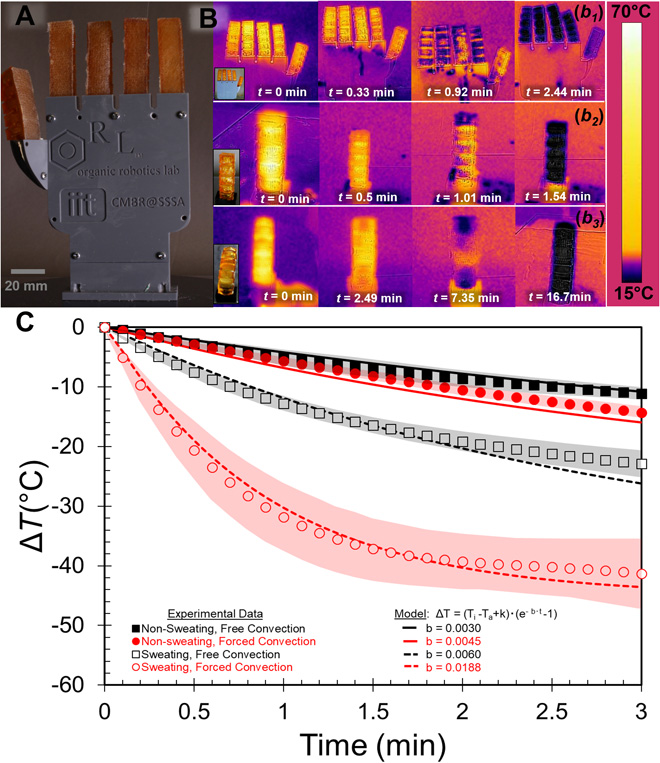
To quantify the thermoregulatory capabilities of a synthetic sweating hand, we mounted five such printed actuators onto a rigid palm (Fig. 4A), raised the temperature of the actuator bodies, and actuated with hot (T = 70°C) water. Figure 4B depicts the actuator surface temperatures as a function of time under both forced and ambient convection (see movie S4). Without pores, no sweating occurred, and the actuator exhibited a modest temperature drop of <6°C min−1 between 0 and 0.6 min with and without convection. Focal hidrosis, however, occurred in the actuators that had dilated pores, and the cooling rate was more than doubled (14.2°C min−1) under ambient conditions. Wind increased evaporation rates by both reducing the relative humidity of the air immediately above the wet surface and reducing the local pressure through the Bernoulli effect. Consequently, under forced convection (~0.165 m3 s−1, wind speed = 5.26 m s−1), a sweating actuator cooled roughly 600% faster (39.1°C min−1) between 0 and 0.6 min than a non-sweating counterpart.
(A) 3D-printed hand: hydraulically controlled fingers assembled in a palm chassis. (B) Temperature variation in hydraulically actuated hand and actuators using thermal camera. (B1) Temperature recorded during the perspiration of a hand under forced convection. (B2) Temperature recorded during the perspiration of a single actuator under forced convection. (B3) Temperature recorded during the perspiration of an actuator under free convection. (C) Sweating test comparison with and without pores in different convection modes (shaded regions are SD; N = 3).
To model the cooling behavior of the actuators, we assume the internal heat resistance of the body to be negligible with cooling occurring due to a combination of convective heat transfer from the surface to the environment and perspiration (i.e., the enthalpy of water evaporation). We also assume a uniform temperature distribution throughout the body due to low membrane thickness and that radiative and conductive heat transfer is negligible (see section S8A for more info). The actuator body’s temperature will decrease to equilibrate with the ambient air’s as written in Eq. 1a (24–28)
(1)where Q is the heat transfer rate from the actuator system, m is the printed actuator mass (6.2 g), cA is the specific heat capacity of the body (J kg−1 °C−1) (experimentally measured; fig. S3, D and E), T is the temperature of the body at any time (°C), h is the convective heat transfer coefficient (W m−2 °C−1), Ta is the ambient temperature (~20°C), t is the time (s), gs is the mass flow rate of evaporated water (kg s−1), and ΔHvap is the enthalpy of water vaporization (kJ kg−1). Rearranging Eq. 1 yields a simple first-order differential equation that can be solved by separation of variables. We impose a boundary condition that when t = 0, T equals Ti, or Ti is the initial body temperature when the actuator is first exposed to the ambient environment temperature Ta. We also assume that water evaporation for a nonporous or “non-sweating” actuator will be negligible (gs = 0). After solving Eq. 1, the drop-in body temperature (ΔT) can be written as a function of time (t), as shown in Eq. 2
(2)
The lumped parameter, b, can be directly calculated for the non-sweating actuators (see section S8), and the resulting model is shown in Fig. 4C. For the sweating actuator, the contribution of evaporative cooling is phenomenologically captured by both latent heat of vaporization and convective heat transfer as above; however, we can also fit the experimental data to yield an effective b, as shown in Fig. 4C.
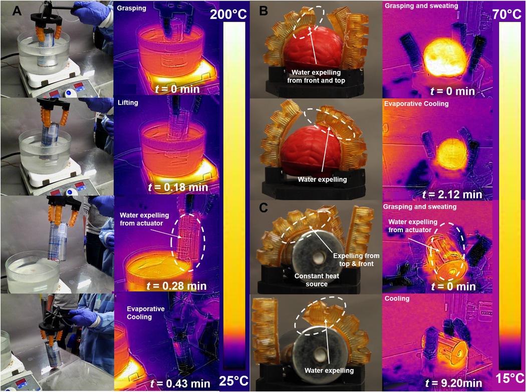
The ability to passively conform to irregular shapes without imparting large stresses to fragile objects is a primary benefit of soft robotic grippers. Manipulators fabricated from our sweating actuators also retain this capability (Fig. 5).
(A) Grasping of metallic object in hot water in vertical state. (B) Grasping of an irregular soft foam. (C) Grasping of a cylindrical metallic object using three-point gripper. (In the reported thermal images, temperature scale bar is changing with time. Moreover, we measured the surface temperature only on the object using customized polygons according to the object shape.)
Unlike previous soft robots, our perspiring actuators can also manipulate the temperature of held objects. In Fig. 5A, a hydraulically actuated three-fingered manipulator removes a hot, empty beverage can from within a bath. When contacting the heated object, the integrated gripper sweats water from within the actuator that can cool the surface (free convection). For example, the temperature of the beverage decreases from ~58° to ~28.5°C (ΔT = ~30°C, see Fig. 5A) in 19 s; a similar time period without sweating only results in a <25°C drop (see fig. S8A). Objects with larger volumetric heat capacities, such as the polyurethane foam and cylindrical metal weight (Fig. 5B), show an even larger (>200%) improvement in cooling rate when manipulated by a sweating gripper than without (see fig. S8, B and C, and section S9 for more details).
DISCUSSION
We developed two hydrogel-composite resins and used multimaterial SLA printing to create finger-like fluidic elastomer actuators with pores that autonomically open and close in response to thermal fluctuation. These 200-μm pores are printed within a PAAm layer that allows for pressurization and actuation (bending angle θ < 80°) at low temperatures. Pore dilation at elevated temperatures provides for sweating that yields a cooling rate over 600% faster than similar non-sweating devices. This ability to thermoregulate via perspiration helps maintain a stable operating temperature that will likely be necessary for reliable control in extreme environments.
Unlike previous attempts for robotic perspiration, our pores autonomically change dimension due to local temperatures (3). Such focal hidrosis allows controlled sweating rates and thermoregulation to specific regions without sensors or controls. In addition, our mechanism does not require a dedicated coolant, instead connecting directly to the internal actuator to use the hydraulic fluid. Although this sweating strategy does hinder actuation amplitude slightly—the non-sweating hydraulic actuator of Fig. 3 (C and D) can obtain bending angles 50% greater at similar volumes of actuation fluid—it can also be used to prevent “overexertion” of the actuators. As the pores expand further at higher temperature, the pressurizing fluid can flow from the internal channel to relax the actuation.
Although we created embodied intelligence by using smart materials that integrate actuation, sensing, and thermoregulation, this work does not represent the ultimate capabilities of such a multifunctional system. The simple circular pore design, for example, is unoptimized, and later attempts could account for the rheology of the fluid (e.g., viscosity and yield stress) and the resulting pressure drop across the fluidic elastomer actuator. Appropriate selection of the hydraulic fluid, pore density, and pore size offer a further means to control the dynamic thermoregulatory response. In addition, other phase transformations beyond the liquid-vapor transition in water can provide for thermoregulation. For example, DSC suggests that the collapsed-to-swollen transition when cooling PNIPAm is endothermic, as noted by the positive heat flow (fig. S4B), and allows the hydrogel actuator to cool below the ambient temperature (20°C) to ~14°C (see Fig. 4B). Further examination of this effect may offer an entirely passive strategy for autonomic thermoregulation. The hydrogel materials reported above are delicate when compared to other engineering elastomers (e.g., polyurethanes and silicones) used in soft robotics. Development of tougher, 3D-printable hydrogels (i.e., double network gels) that maintain our desired thermoresponse will enable robust sweating actuators. Last, similar to nature, evaporative cooling offers limited capabilities underwater or in a saturated atmosphere (with very high relative humidity >90%), which would require alternative thermoregulatory strategies.
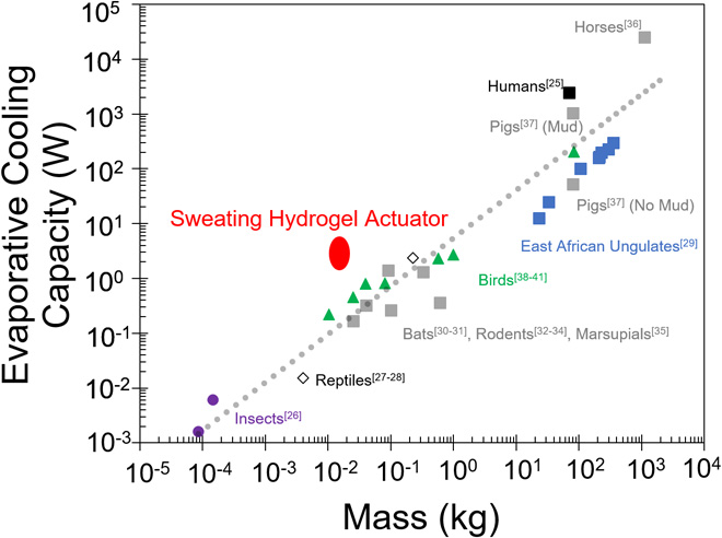
Changes in metabolic rate, exertion level, or environmental temperatures require organisms to implement various thermoregulatory strategies. For cooling, animals can dissipate heat through conduction, convection, radiation, and evaporation. Because the rate of temperature dissipation for the first three processes is dependent on the temperature difference between the body and environment, evaporation is the most successful at lowering body temperatures below ambient (29). Evaporative water loss can be accomplished behaviorally (e.g., wallowing in mud) or physiologically (e.g., respiratory evaporation, salivating, or perspiration) (30). Figure 6 compares the evaporative cooling capacity of numerous animals relative to their body mass (30–46). As shown by the line of best fit (gray dashes), regardless of evaporative strategy, most animals evolved to have roughly 15 W kg−1 of cooling capacity. In our actuator system, we estimated the contribution of evaporative cooling by comparing the thermoregulatory performance of our sweating actuator to that of corresponding non-sweating actuators. This analysis yields an estimated evaporative cooling capacity at a total actuated mass of 15 g (mactuator = 6.2 g, mactuating fluid = 8.8 g). The resulting capacity ~107 W kg−1 is >300% greater than that found in biology; the extraordinary sweating capability of humans and horses only provide for >35 W kg−1 (see section S8, A to C, for a more detailed analysis) (2, 41). The cost of this high cooling capacity comes at the increased flow rate of fluid required to maintain the same actuation amplitude (Fig. 3D). Similar to animals that ingest food and water from their environment to sustain thermoregulated activity, our demonstrated system eventually requires a means to replenish lost water during extended operation.
Beyond thermoregulation, sweating actuators may offer additional beneficial features. Animals use eccrine glands and sweat to release chemical substances like pheromones in their environment for social communication. Fluid excretions could be used to change the friction between surfaces and allow for smooth movement, particularly useful for directing the locomotion of crawling or sliding robots (47). The ability to selectively elute liquids from the robot body also provides for many other opportunities including “digesting” and absorbing nutrients, catalyzing reactions, removing contaminants from the surface, or coating the surface of the robot with a protective layer.
MATERIALS AND METHODS
Materials
AAm, NIPAm, N,N′ methylene bis(acrylamide) (MBA), hydroquinone (99%), and Ludox HS-30 colloidal silica were purchased from Sigma-Aldrich (St. Louis, MO); triethanolamine (>99%, Neta Scientific), and riboflavin were obtained from Neta Scientific (Hainesport, NJ). Gelest Inc. (Morrisville, PA) provided 3-(trihydroxysilyl)-1-propane sulfonic acid [SIT; 30 to 35 weight % (wt %)].
Synthesis and functionalization of silica and iron oxide nanoparticles
The modification of silica was conducted according to previously published research (12). Briefly, Ludox HS-30 colloidal silica and SIT were diluted by four volumes of deionized (DI) water. Then, the silica solution was added to the vigorously agitated SIT diluted solution. pH was then adjusted to 5 by 1 M sodium hydroxide solution. The condensation was performed at 70°C for 24 hours under vigorous agitation. The product was purified by dialysis in the DI water using 10,000 molecular weight cutoff tubing to get rid of unreacted small molecules. After the dialysis, the solution was subjected to cation exchange to replace all the surface cations to protons. Iron oxide nanoparticles were synthesized through chemical coprecipitation using ferric chloride and ferrous chloride as precursors. Briefly, ferric chloride and ferrous chloride were mixed in the water solution at the molar ratio of 2:1 (Fe3+/Fe2+). This solution was then transferred drop by drop into an ammonium hydroxide base solution (28% NH3 in H2O, 7.5 wt %) with vigorous stirring. Afterward, the solution was heated to 70°C and maintained for 30 min and then at 90°C for 90 min. The reaction was kept at inert condition until cooled. The iron oxide nanoparticles were the products in the solution.
3D printing of hydrogel resins
NIPAm/AAm resins are composed of 25 mole percent (mol %) of AAm and 75 mol % NIPAm in a 40% (w/v) solution. MBA (1 mol %) was added as the chemical cross-linker. Solutions containing certain amounts of functionalized silica solution, iron oxide nanoparticle solution, and radical scavenger hydroquinone in DI water were used as the solvent (see Fig. 1A). Hydroquinone is mainly used as a radical scavenger and to improve the printed resolution and pot life. An Ember SLA printer (open access) by Autodesk with an LED (light-emitting diode) projector as the light source (λ = 405 nm, the irradiance of Je ≈ 22.5 mW cm−2) controlled by open-source software (Print Studio, Autodesk) was used to print the actuator. The 3D design of the actuator was developed using SOLIDWORKS 2017. The printing settings for curing each layer were as follows: for AAm, layer height (LH) was 150 μm at 22-s exposure time; for NIPAm, LH was 250 μm at 59-s exposure time. To print the multimaterial actuator, we developed a protocol where we paused the printer at the 60th layer (hprinted body = 15 mm) and replaced the NIPAm material tray with an AAm material tray and then restarted printing the dorsal layer of the finger (hdorsal layer = 1.5 mm). The printed actuators are shown in fig. S1 (A and B).
Photo-rheology
We characterize the resins’ compatibility with SLA printing through oscillatory shear rheology (DHR-3, TA Instruments) at constant frequency and amplitude (ϖ = 1 Hz and Γ = 1% strain) during photo-exposure. In this parallel plate geometry (d = 20 mm, gap = 1 mm), the transparent, acrylic bottom plate connects to an ultraviolet (UV) light source (OmniCure Series 1500, Lumen Dynamics) and UV filter (λ = 400 to 500 nm) through a coupled light guide. A radiometer (Silver Line UV 230-410 nm) placed directly on top of this plate measured an irradiance of Je = 7.6 mW cm2 (measured rheological parameters are shown in Fig. 2A and fig. S2, A and B).
Dynamic mechanical thermal analysis
We used dynamic mechanical thermal analysis (DMTA) with TA Instruments DMA Q800 on prepared samples (5-mm-diameter and 5-mm-thick circular disc) to characterize the mechanical properties of both materials. Before measurement, samples were equilibrated at temperature (30°, 40°, 60°, and 80°C) for at least 1 hour in a water bath. This soak also removed free monomers and photoinitiator from the gel to improve mechanical stability. We then ran the test seven times for each temperature with each material, recording the compressive stresses and strains (fig. S3, A and B). We also performed cyclic tests for PAAm and NIPAm at 30° and 60°C using DMTA setup. We report all results in fig. S3 (C and D).
Swelling test of hydrogel
We performed the measurement of the equilibrium swelling ratio (SR) of PNIPAm and PAAm hydrogels using gravimetry. We define the swelling ratio as the mass ratio of the swollen sample to the mass of printed sample (Eq. 3)
(3)where M is the mass of the sample in its swollen or collapsed state, and Mp is the mass of sample in its initially printed state. We measured swelling ratio of the base hydrogel materials at varying time periods (0 to 64 min) of immersion in different temperature (30°, 40°, 50°, 60°, 70°, and 80°C) water as shown in Fig. 2 (C and D). To remove any surface water, we placed each sample on cellulose paper and then immediately measured the mass. In addition, we measured the swelling ratio of hydrogel after a prolonged submersion (t > 12 hours) and reported this equilibrium behavior in fig. S4A. Figure 3B reports the swelling ratio of the multimaterial actuator as measured in a similar manner.
Measurement of pore size diameter
Apart from the mass swelling ratio (SRmass), we also measure the area swelling ratio (SRarea, Eq. 4). To perform this experiment, we printed square sample of PAAm and PNIPAm with different pore size diameters (200, 500, 1000, and 2000 μm). After printing the square sample, we placed the samples into a glass vial with water at different temperatures for 4 hours. We then took the samples from the vial, removed the surface water, and collected the images of a reference ruler and the swollen or shrunken pores using a high-resolution camera (Canon EOS 80D, 24.2 megapixels). We then quantified the pore dimensions from these images with ImageJ software (N ≥ 8)
(4)where A is the area of the pore under examination and Ap is the initial area of the pore after printing. We performed pore reversibility tests by again quantifying the swelling and shrinking of printed PAAm samples (10 mm by 10 mm by 2 mm with 2-mm-diameter pores). For rapid measurements, we soaked the sample in hot water (at 80°C) for 1.5 hours and then collapsed the sample for ~20 min in an unfavorable environment for five cycles. We measured the mass swelling ratio gravimetrically and the area swelling ratio using a camera and image process software (ImageJ). All the results are reported in fig. S5 (A to C).
Bending angle measurement
For the bending test, we first connected the printed actuator to a silicone tube (3 mm diameter) and affixed the device on a 3D-printed stand. We secured the connection between the tubing and actuator by first inserting the tube with a small coating of cyanoacrylate adhesive and then depositing more uncured hydrogel ink to the junction before UV exposure (48, 49) to teach others how to replicate this technique. This method provided sufficient adhesion to prevent failure at junction. After fixing the actuator on stand, we pressurized the actuator using a programmable syringe pump (NE-1000, New Era Pump Systems Inc.) connected through a pressure sensor (fig. S6). A custom LabVIEW code (National Instruments) that interfaced with the pump and sensor collected pressure-volume data. During the experiment, we recorded the video using a high-resolution camera (Canon EOS 80D, 24.2 megapixels) and set the pump at 5 ml min−1. Image analysis using the image processing toolbox in MATLAB (MATLAB 2018a, MathWorks Inc.) yielded the bending angle. Experimental results (repeated three to four times each) are reported in Fig. 3 (C and D), fig. S5 (D and E), and movie S3.
Thermoregulation
We measured the thermal behavior of finger actuators in four modes: with and without sweating under both free and forced convection. In addition to dipping the actuator in a heated bath, we also injected preheated water at the desired temperature into the actuator. During the injection of water, we recorded the bending motion (normal camera) and temperature drop (thermal camera FLIR E4; resolution, 80 pixels by 60 pixels; thermal sensitivity, <0.15°C; accuracy, 2°C; and object temperature range, −20° to 250°C) for 30 min (see setup in fig. S6 and movie S4). To simulate forced convection, we used a small commercial fan (Honeywell, HT-900, 350 CFM). We repeated the experiments at least three times for statistical significance. After recording the thermal images from the camera, we used FLIR tools software to analyze the temperature on the dorsal side of the actuator with respect to time. We measured maximum, minimum, and average temperatures throughout the top surface area using a consistent, user-defined rectangular area at different time intervals. We used a curve-fitting method to analyze the data and compared it to the model (using exponential/cubic type, R2 value varies between 0.94 and 1). All the temperature data with sweating and without sweating and natural cooling of the actuator and hand are reported in Fig. 4 (B and C) and fig. S7.
Grasping test
For the grasping test, we fabricated a gripper with three fingers and oriented it at 120° from each other and actuated it by a single syringe pressure source (BD, 60 ml). We dipped a thin cylindrical metallic object (aluminum soda can, ~12 g) in 100°C water for 10 min to equilibrate and then actuated the three-armed gripper and removed the object from within the beaker. While grasping the object, heat transfer caused our actuator to begin sweating (the large thermal gradient rapidly opens the pores) and cool both the surface of the actuators and the object during the manipulation. We tracked this thermoregulation via thermal imaging as previously described (Fig. 5A and movie S5). Similarly, we heated an additional metallic object (or foam) and placed it between the arms of the gripper. We then pressurized the actuators to show the adaptability: The low modulus of the hydrogel body enables the gripper to adeptly conform to irregular or curved surfaces. Again, the elevated temperature caused the actuator pores to expand and release water to thermoregulate the actuator and manipulated object (Fig. 5, B and C, and movie S5).
SUPPLEMENTARY MATERIALS
robotics.sciencemag.org/cgi/content/full/5/38/eaaz3918/DC1
Section S1. Temperature dependence of mechanical properties
Section S2. Gel fraction analysis
Section S3. UV-visible spectroscopy
Section S4. Photo-differential scanning calorimetry (photo-DSC)
Section S5. Differential scanning calorimetry (DSC)
Section S6. Physical property measurement system (PPMS)
Section S7. Heat transfer test in high and low surface area
Section S8. Modeling of heat capacity in finger-like actuators
Section S9. Thermal manipulation of hot objects
Fig. S1. 3D-printed actuator.
Fig. S2. Hydrogel ink characterization.
Fig. S3. 3D-printed material characterization.
Fig. S4. Thermal property characterization.
Fig. S5. Swelling and bending tests.
Fig. S6. Experimental setup for testing bending, sweating, and grasping.
Fig. S7. Effect of heat transfer rate with high and low surface area hydrogel actuator.
Fig. S8. Sweating and grasping tests with different types of hot objects.
Movie S1. Printing.
Movie S2. Color change.
Movie S3. Bending.
Movie S4. Sweating.
Movie S5. Grasping.
REFERENCES AND NOTES
- ↵
C. McDougall, Born to Run: A Hidden Tribe, Superathletes, and the Greatest Race the World Has Never Seen (Knopf, 2009).
- ↵
A. C. Guyton, Basic Human Physiology: Normal Function and Mechanisms of Disease (W. B. Saunders Co., 1971).
- ↵
T. Kozuki, H. Toshinori, T. Shirai, S. Nakashima, Y. Asano, Y. Kakiuchi, K. Okada, M. Inaba, Skeletal structure with artificial perspiration for cooling by latent heat for musculoskeletal humanoid Kengoro, in Proceedings of the 2016 IEEE/RSJ International Conference on Intelligent Robots and Systems (IROS) (IEEE, 2016), pp. 2135–2140.
- ↵
- ↵
- ↵
-
A. D. Marchese, C. D. Onal, D. Rus, in Experimental Robotics (Springer, 2013), pp. 41–54.
- ↵
- ↵
J. E. Hatch, Aluminum: Properties and Physical Metallurgy (ASM International, 1984).
- ↵
- ↵
- ↵
- ↵
- ↵
- ↵
- ↵
- ↵
M. Ebara, Y. Kotsuchibashi, R. Narain, N. Idota, Y.-J. Kim, J. M. Hoffman, K. Uto, T. Aoyagi, Smart Biomaterials (Springer, 2014).
- ↵
- ↵
- ↵
- ↵
- ↵
F. P. Incropera, A. S. Lavine, T. L. Bergman, D. P. DeWitt, Fundamentals of Heat and Mass Transfer (Wiley, 2007).
-
R. K. Rajput, Heat and Mass Transfer (S. Chand, 2007).
-
P. Nag, Engineering Thermodynamics (Tata McGraw-Hill Education, 2013).
-
B. R. Sehgal, Nuclear Safety in Light Water Reactors: Severe Accident Phenomenology (Academic Press, 2011).
- ↵
K. Raznjevic, Handbook of Thermodynamic Tables and Charts (Hemisphere Publishing Corporation, 1976).
- ↵
W. Dawson, G. Whittow, in Sturkie’s Avian Physiology (Elsevier, 2000), pp. 343–390.
- ↵
C. Jessen, Temperature Regulation in Humans and Other Mammals (Springer Science & Business Media, 2012).
- ↵
- ↵
- ↵
- ↵
- ↵
Funding: This research was supported, in part, by Office of Naval Research Young Investigator Program (N00014-17-1-2837). This work made use of the Cornell Center for Materials Research Shared Facilities, which are supported through the NSF MRSEC program (DMR-1719875). A.K.M. acknowledges Scuola Superiore Sant’Anna and Istituto Italiano di Tecnologia, Italy, for their support during a visiting fellowship at the Organic Robotics Laboratory, Cornell University. Author contributions: A.K.M., T.J.W., and W.P. designed and conducted experiments and wrote and edited the manuscript. K.W. and P.X. conducted experiments and edited the manuscript. E.P.G., B.M., and R.F.S. obtained resources, designed experiments, and edited the manuscript. Competing interests: The authors declare that they have no competing interests. Data and materials availability: All data needed to evaluate the conclusions in the paper are presented in the main manuscript and/or the Supplementary Materials. Additional data are available from the authors upon request.
- Copyright © 2020 The Authors, some rights reserved; exclusive licensee American Association for the Advancement of Science. No claim to original U.S. Government Works